Driving a brushless motor precisely
Making the circuit
My task this week is to make circuits and program to drive a brushless motor (BLM) very precisely (and slowly). By precise I meant I can set the angle of the motor to the precision of 0.03deg, even much more accurate than common stepper motor which is around 1.8deg. Common brushless motor esc (electronic speed controller) only deal with speed instead of precise angle. So I designed my own motor driver with ATmega328p microcontroller and SN754410 quadruple half-H bridge driver. The control board produce PWM signals to tune the driving board output. I tried with A4953 H bridge first in previous weeks but found it doesn't work with 5V power input which I desire to use on my final project.
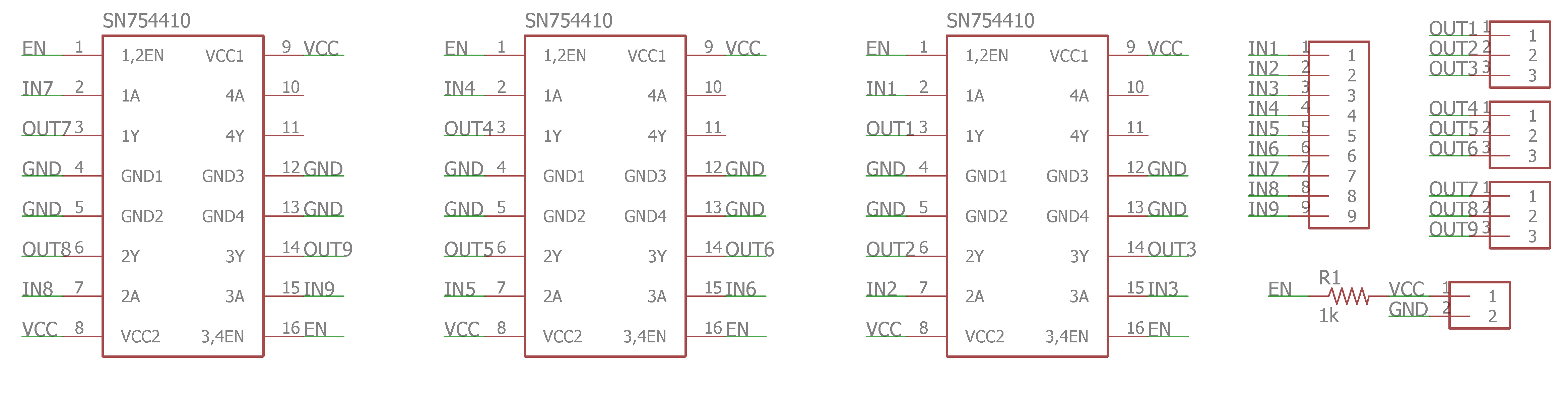
Control board schematic: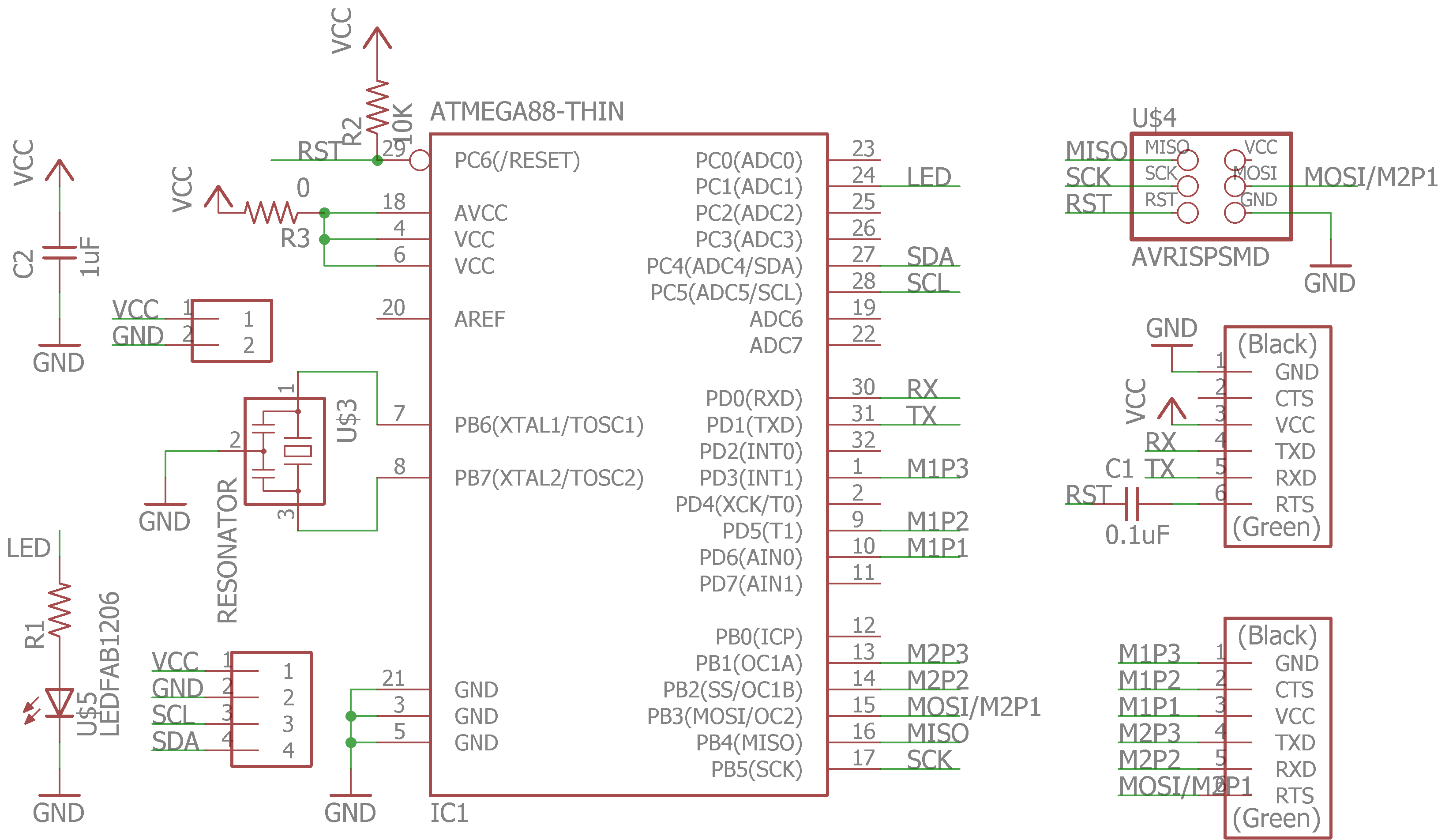 Driver board schemetic:
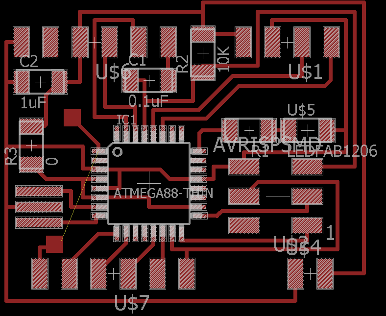
 Control board:
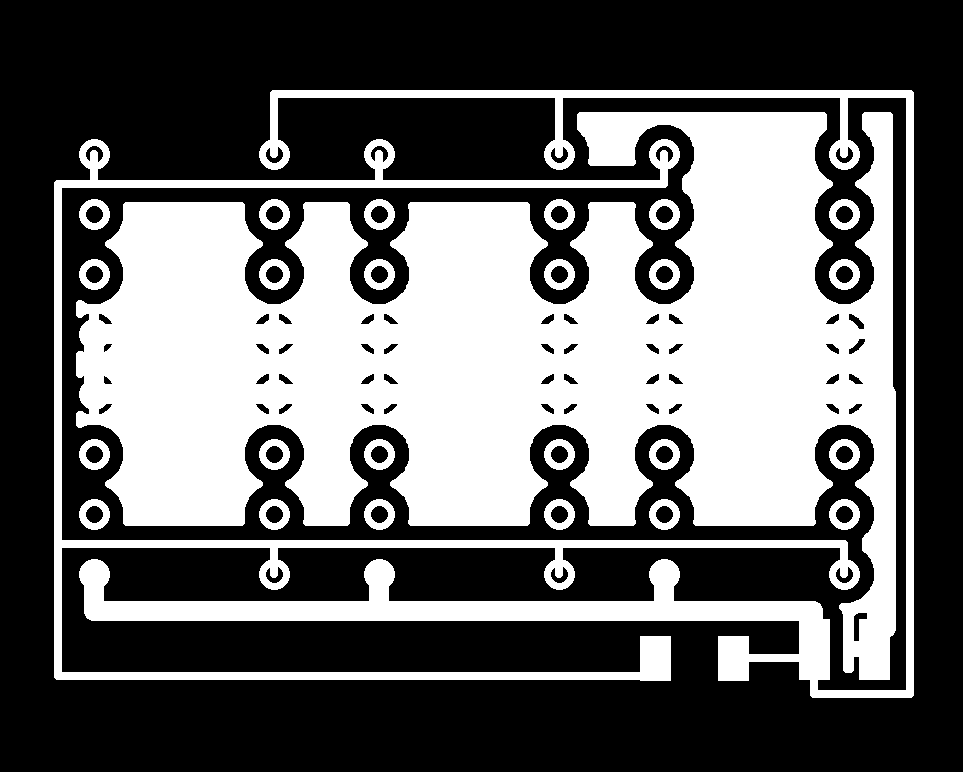
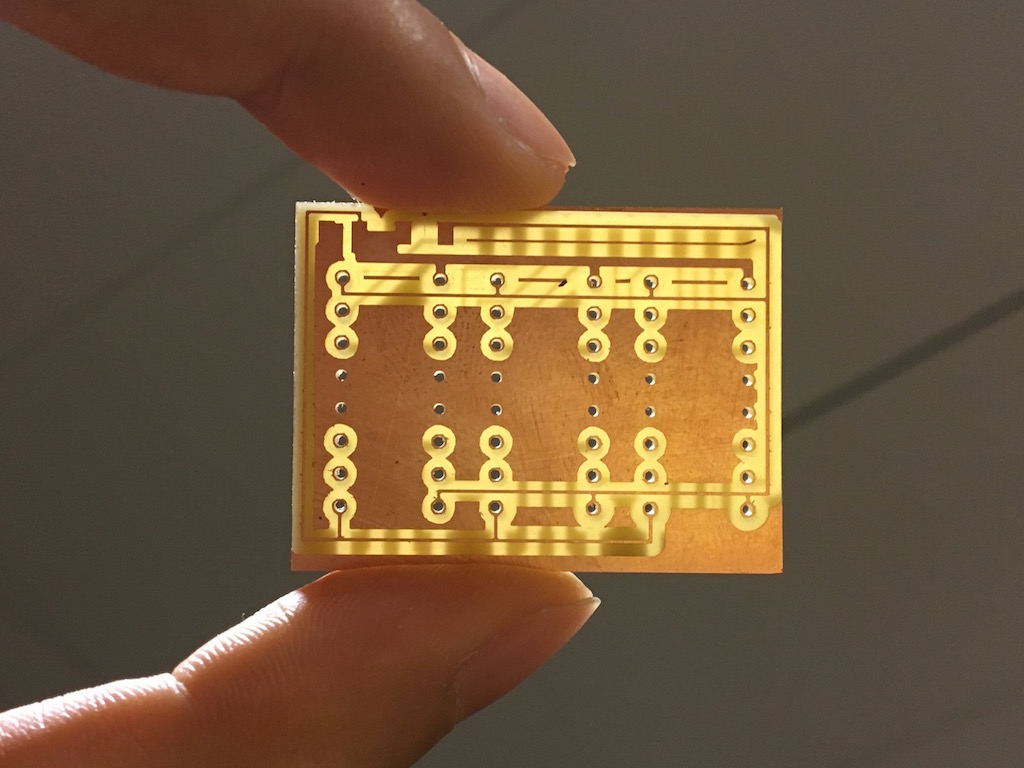
 Driver board (double sided):
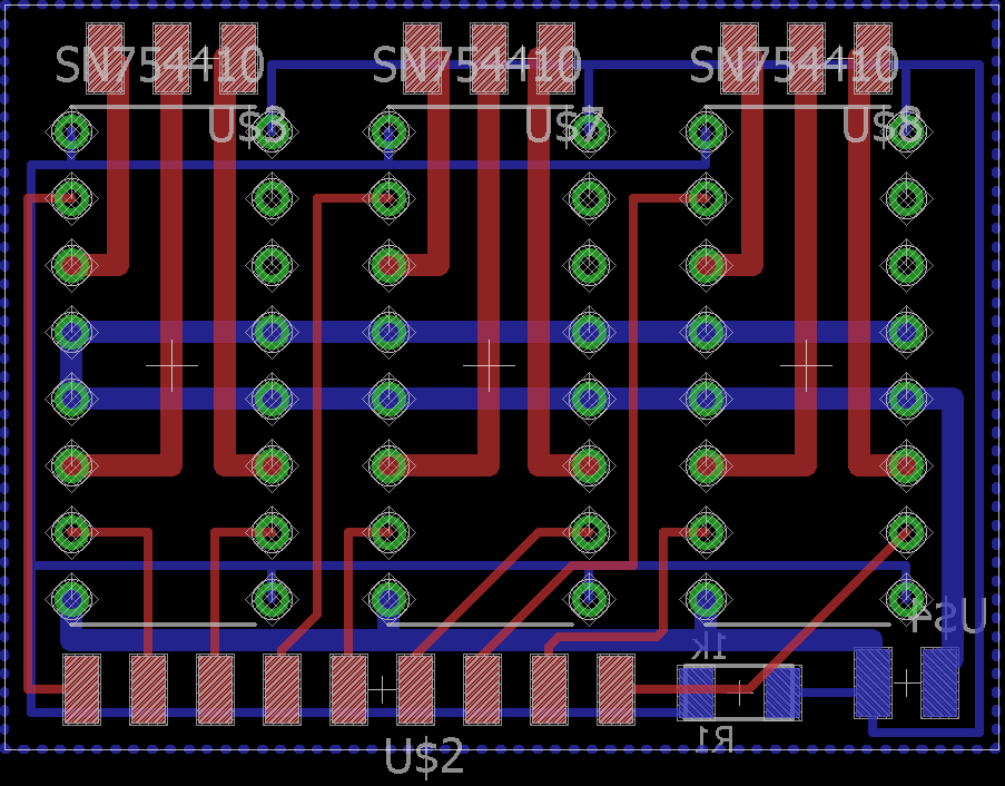
As I found it's impossible to route the driver without wires crossing each other, I used two side board design. The red is on top layer while blue is on the bottom layer. For better heat dissipation I also added ground plane in eagle on the bottom layer. The part were large current will flow is routed with thicker wires.
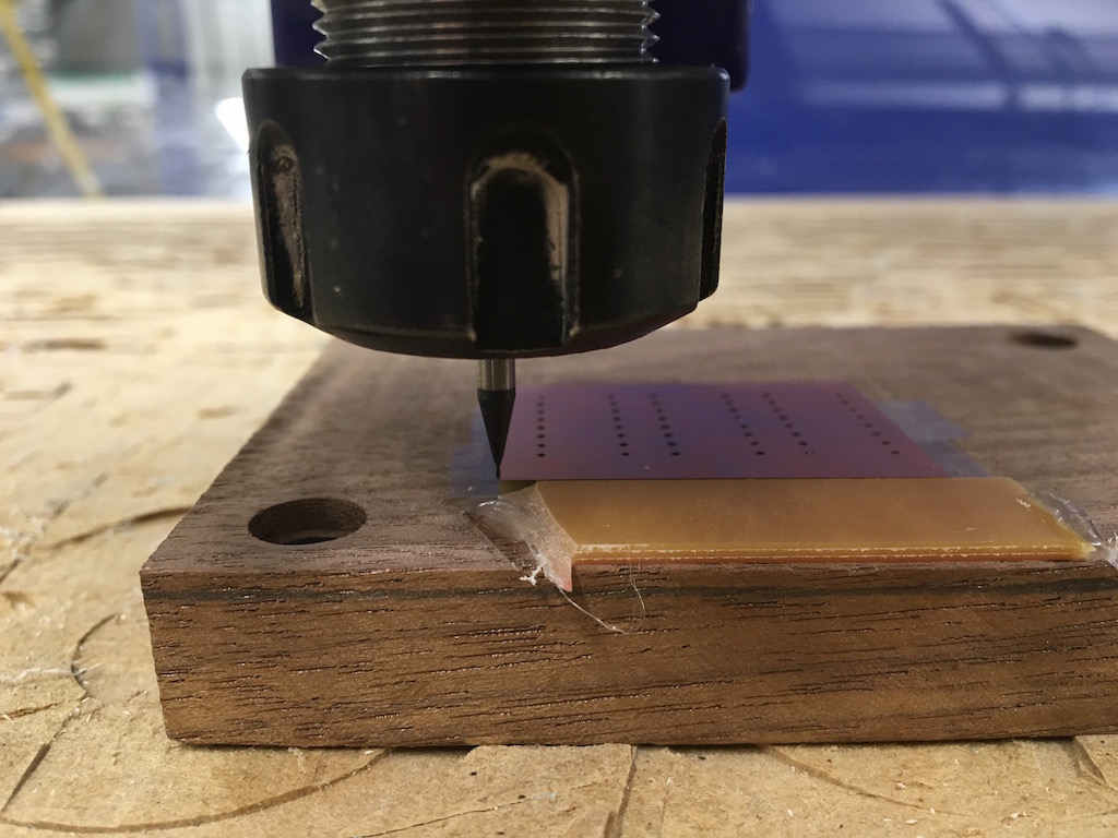
To make the double sided board, I inverted the png file and align the mill to the corner of the cutted board after flipping it over. The following images shows the alignment after oneside is milled and drilled. To ensure the orientation of the board kept the same after flipped over, I glued a strip of PCB onto the substrate to help with alignment. The alignment turns out to be pretty good as shown.
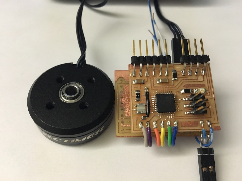
After cutting I also added a large capacitor (100uF) between Vcc and ground to filter out voltage fluactuations caused by switching the MOSFET. And the two board are connected through six signal wires which can drive two BLMs. The control board can also communicate through I2C which can read the gyroscope and accellarometer.
Driving the BLM, theory and program
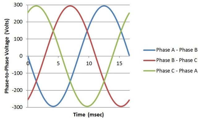
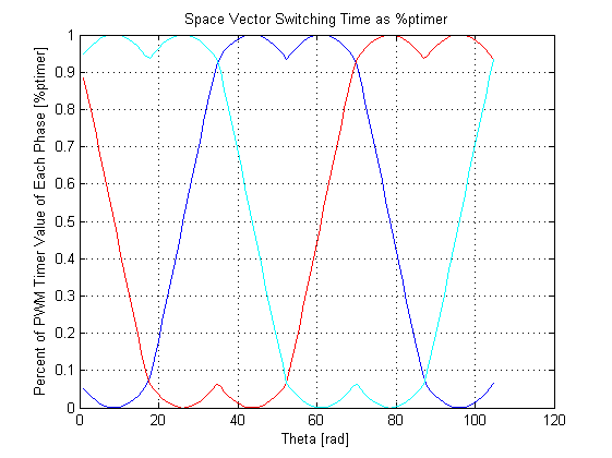
BLMs has three phases of windings which controls the vector of produced magnetic field. To rotate the runner, we modulate the voltage input on each winding. There are two common driving voltage patterns, one is sinosoidal, another is space vector modulation. The former is just three sine wave shifted by 2/3pi each. The latter is more complicated but essentially the difference between each voltage is sine wave and have the benefit of larger output capability under the same Vcc. I tried both of them, below is showing the sine wave code.
In the code, I used three PWM pins on OCR1A,B and OCR2A and sync the two counter. The frequence of the PWM is ~80KHz with prefactor one, if the clock prefactor set to 8 it will produce a high pitch noise ~10KHz. The lookup table was calculated in matlab.
	#include <avr/io.h>
	#include <util/delay.h>

	//sinosoidal wave
	const uint8_t P1[] = {127,130,133,...};
	const uint8_t P2[] = {235,234,232,...};
	const uint8_t P3[] = {19,17,16,...};

	void stepforward(){
		static uint8_t i = 0;
	   if (i == 255) {
	      i = 0;
	   }
	   else{
	      i++;
	   }
	   OCR1A = P1[i];
	   OCR1B = P2[i];
	   OCR2A = P3[i];

	}

	int main(void) {
	   // set clock divider to /1
	   CLKPR = (1 << CLKPCE);
	   CLKPR = (0 << CLKPS3) | (0 << CLKPS2) | (0 << CLKPS1) | (0 << CLKPS0);

	   DDRB = (1 << PB1) | (1 << PB2) | (1 << PB3);
	   DDRC = (1 << PC1);

	   GTCCR = (1 << TSM) | (1 << PSRSYNC) | ((0 << PSRASY));
	   // halt timers; (1 << PSRASY) halt timer2, (1 << PSRSYNC) halt timer 0&1

	   TCCR1A |= (1 << COM1A1) | (1<< COM1A0) | (1 << COM1B1) | (1<< COM1B0);
	   TCCR1A |= (1 << WGM10); // phase correct 8bits mode
	   TCCR1B |= (1 << CS10); //1 prescale
	   OCR1A = P1[0];//Cmm[0]; // compare value, 16bit
	   OCR1B = P2[0];

	   TCCR2A |= (1 << COM2A1) | (1<< COM2A0) | (1 << COM2B1) | (1<< COM2B0);
	   //set on upcounting, clear on down couting

	   TCCR2A |= (1 << WGM20); // phase correct 8bits mode
	   TCCR2B |= (1 << CS20);
	   OCR2A = P3[0]; // compare value, 8bit

	   TCNT1L= 0x00;
	   TCNT1H= 0x00;
	   TCNT2= 0x00;

	   GTCCR = 0;//release all timer

	   while (1) {
	        stepforward();
		   _delay_ms(50);
	   }
	}
Testing and trouble shooting
The code does rotate the motor and the speed is controlled by the delay tiem. However, there is problem: the motor doesn't rotate smoothly as it suppose to. Instead it rotate and stop for a moment and then rotate again. And I counted it does that for 42 times in each round. Consider the 12N14P configuration of the winding, it means in each period it stopped by six times. This motion is shown in the following screen together with the oscilloscope pattern.
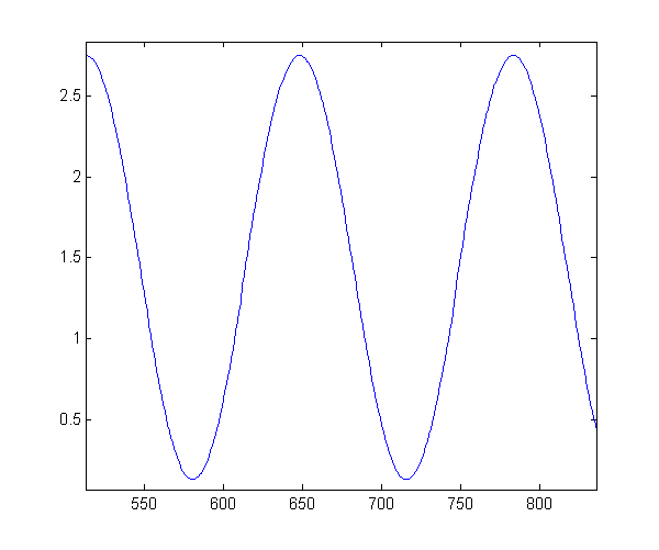
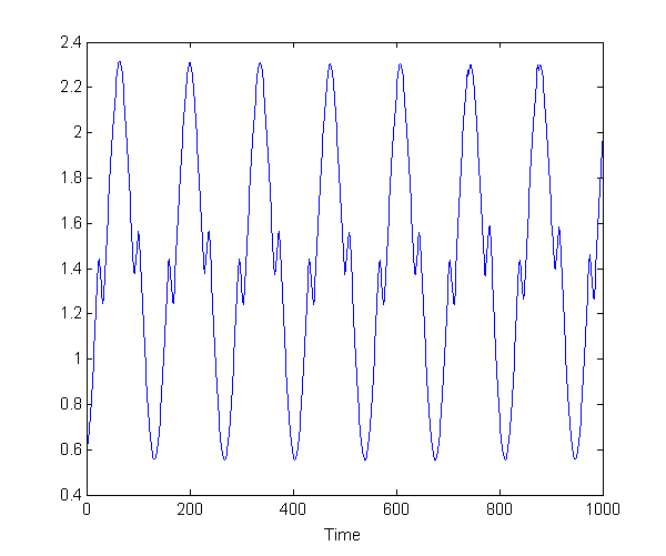
There is something weird in oscilloscope however it's too complicated to analysis. Then I tried to measure the DC output from the driver board with the motor disconnected (left) vs connected (right). As can be clearly seen, the left one is perfect sine wave as I programmed. But once the motor is connected the output voltage is skewed.
DC measurement setup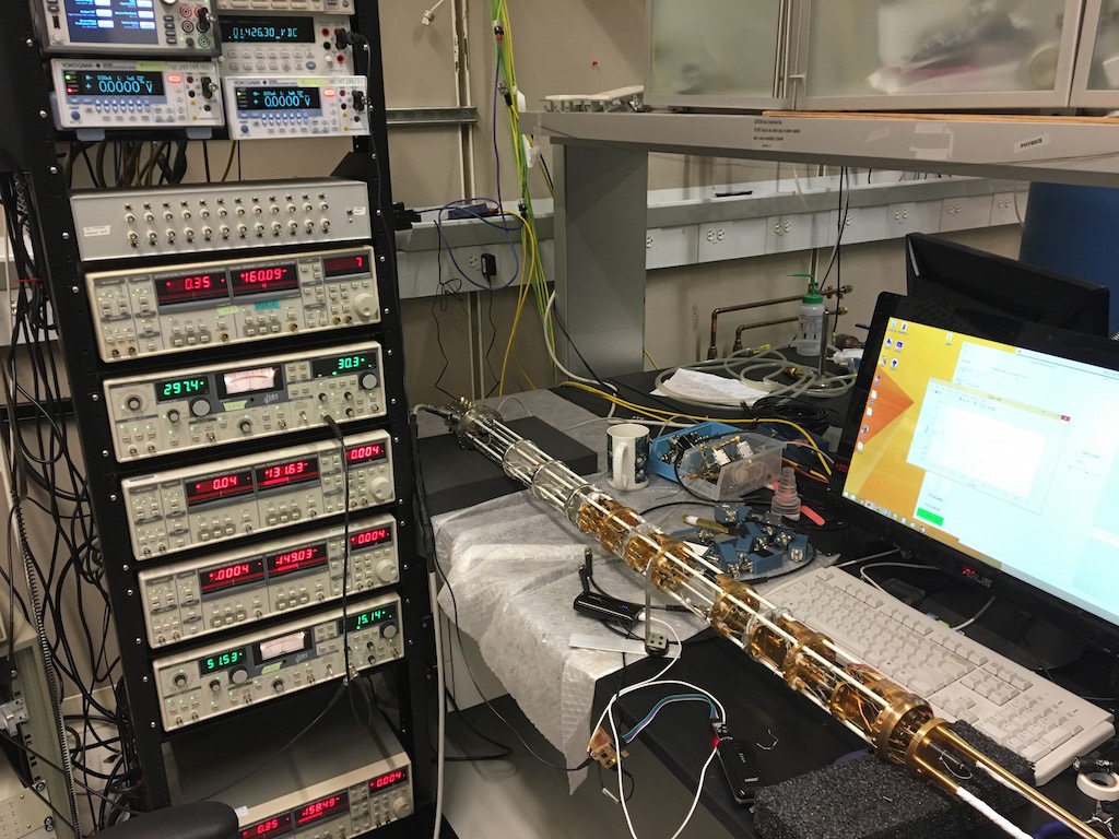
Waveforms: motor disconnected (left) vs connected (right)
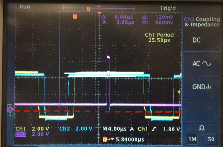
Then I did more test with oscilloscope by measuring all three output pins and move the motor really slowly so I can see what's going on in the PWM signals.
Just looking at one of the frame in the video we notice not all the on/off state are at the same voltage level. Some part the pin voltage even go below ground (marked with red dashed lines) or above Vcc.
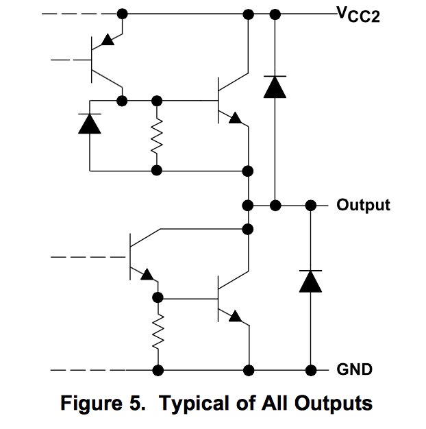
This makes me realized when the motor draws a large current from the driver, there is voltage drop cross the MOSFET inside the H-bridge driver. This won't cause much problem if it is driving a resistor other than a little bit lower output voltage. But when we drive a motor with large inductance, which the current is not in phase with the voltage, the voltage output can depend on both the on/off state and the way current is flowing. This result in the problem of when current direction reverse by changing the duty cycle, so does the voltage deviation from ground or Vcc (voltage drops on MOSFET or the diode). And this caused the motor to stall when the current direction changes.
There is no easy and elegant solution to this problem that I can think of. So I plan to re-calibrate the angle-PWM relation by measuring the rotation angle at each PWM output. As I don't have a encoder, I plan simply use the accelerometer I made two weeks ago and fix it onto the rotator and measure direction of G-force. And pass the information to computer to generate a calibrication curve.